Price:
US$34.99
Free Shipping
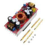
1500W 30A High Power DC-DC Constant Voltage Constant Current Step-up Power Module Boost Converter 12V 24V 48V To 48V 60V 72V

Compatibility
To confirm that this part fits your vehicle, please enter your vehicle's details below.
-
Year:
Select
-
Make:
Select
-
Model:
Select
-
Submodel:
Select
-
Trim:
Select
-
Engine:
Select
- Clear All
This part is compatible with 0 vehicle(s).
Show all compatible vehicles
Show all compatible vehicles
This part is compatible with 1 vehicle(s) matching
This part is not compatible with
Recent searches
- Year
- Make
- Model
- Submodel
- Trim
- Engine
Specification:
Module properties: non-isolated step-up module (BOOST)
Input voltage: DC 10V~60V (10~30V input voltage, maximum current 30A; 31~60V input voltage, maximum current 25A)
Quiescent current: 15mA (12V step up to 20V, the higher output voltage the quiescent current will increase)
Output voltage: 12~90V continuously adjustable, please make sure output voltage higher than input.
Output current:20A Max,please enhance heat dissipation when output current higher than 15A
Constant current range: 0.8~20A(±0.3A)
Input reverse polarity protection: Yes(150A MOS)
Short circuit protection: Yes (input 30A fuse)
Low battery protection: Yes(8-50V adjustable) self-recovery type
Operating temperature: -40~ + 85℃(ambient temperature if too high, please enhance heat dissipation)
Operating frequency: 150 KHz
Conversion efficiency: 92% ~ 97%(efficiency related with input,output voltage, current and voltage difference.)
Output power: = Input voltage * 30A,such as: Input 12V * 30A = 360W,when input 12V the maximum power is 360W.
Input voltage * 30A Such as: input 24V * 30A = 720W, that is when input is 24V the maximum power is 720W
Module Size: 130 x 52 x 85mm
Installation: 4pcs 3mm screw copper pillar
Features:
1. With airfoil with airfoil, the heat dissipation effect is very good, and the output power is larger (the power can be up to 1200W when 48V input and fan are added).
2. The temperature-controlled fan, combined with the hydraulic bearing fan, achieves a very good balance between noise and heat dissipation. When the load is light, the fan does not rotate, and the fan automatically turns on after the load weight reaches 60 degrees. Can effectively reduce noise and extend life.
3. The main power tube insulation board is made of high-grade alumina, and the thermal conductivity is 10 times that of ordinary insulation pads.
4. Adopt 100V 210A TO-247 large package power tube, with large power margin and good dynamic response.
5. Large-size iron-silicon-aluminum magnetic ring, using 3 1.2 pure copper enamel enveloping lines, low heat and high efficiency.
6. New design, conversion efficiency of up to 98.1% (see the data sheet efficiency conversion curve below for details).
7. The brand 3296W multi-turn potentiometer has high adjustment precision and small drift.
8. Constant copper wire output current sampling, constant current stable temperature drift small.
9. The undervoltage protection is adjustable, which can effectively protect various batteries and can also be used for solar cells.
10. With constant current function, it can be used for battery car boost, battery charging and so on.
11. Input two 20A fuses in parallel to protect the risk of accidental short circuit output.
12. Three indicators: undervoltage, overcurrent, power indication, working status at a glance.
13. Both input and output use high frequency capacitors, low output ripple, low heat generation and long life.
14. The input and output have newly added MLCC ceramic capacitors, and the output ripple is significantly reduced. It is about 100 millivolts at 48V to 72V 4A.
Operation Guide:
Voltage regulation:
When the power supply is unloaded, use a flat-blade screwdriver to adjust the output terminal "V-ADJ" potentiometer (marked in the figure below) to increase clockwise and counterclockwise to adjust). Because the output capacitor capacity is large, the output voltage is When the high voltage is adjusted to a low voltage, the reaction will be slower. The adjustment of the instrument is smaller.
Current regulation:
Adjust the "CC A-ADJ" potentiometer counterclockwise for about 30 turns, set the output current to the minimum, connect the load such as the LED battery, and adjust the "CC A-ADJ" potentiometer clockwise to the current you need. For battery charging, after the battery is discharged, it is connected to the output, and adjust the CC A-ADJ to the current you need. When charging, be sure to use the discharged battery to adjust the battery. The more the charge, the smaller the charge current. The default output ESC is shipped to 10A. If we need to adjust the current value of the instructions or message. Do not use the short-circuit output to adjust the current, the circuit structure of the boost module can not be adjusted by short circuit.
Enter low battery protection adjustment:
Low battery protection is mainly to prevent over-discharge of the battery when the input power is the battery. The battery voltage is too low to damage the power module and the battery. When the input is a switching power supply, the low voltage protection should also be set.
Method 1: For example, set 12V battery low battery protection. Connect a voltage of 11V to the input terminal of the power module. Use a flat-blade screwdriver to adjust RV1 (clockwise protection voltage value is increased, counterclockwise protection voltage is turned down) until the UVLO lamp is on. At this time, the low battery protection voltage is 11V. When the voltage drops to 11V, the power module does not rise (the input voltage is equal to the output voltage). Only after the input voltage is higher than 11V, the power supply starts to resume boosting.
Method 2: Input the battery or switch power supply. If the UVLO lamp on the board is off, adjust the RV1 potentiometer clockwise, brighten the UVLO lamp, and then turn it clockwise two turns. If the UVLO lamp is on, turn the RV1 potentiometer counterclockwise, turn off the UVLO lamp, and then turn it two turns. (Adapt to 10V-45V voltage)
Precautions:
(1) The output positive and negative poles cannot be reversed and cannot be short-circuited.
(2) If used for electric vehicle boost drive power supply, the input voltage must be 24V or more. The electric vehicle power is less than 500W. Because the electric motor is an inductive load, the current will be large at the moment of starting and uphill. There must be sufficient


