
Price:
US$1.96
Free Shipping
DIY Analog Electronic Candle Production Kit Ignition Control Simulation Candle Kit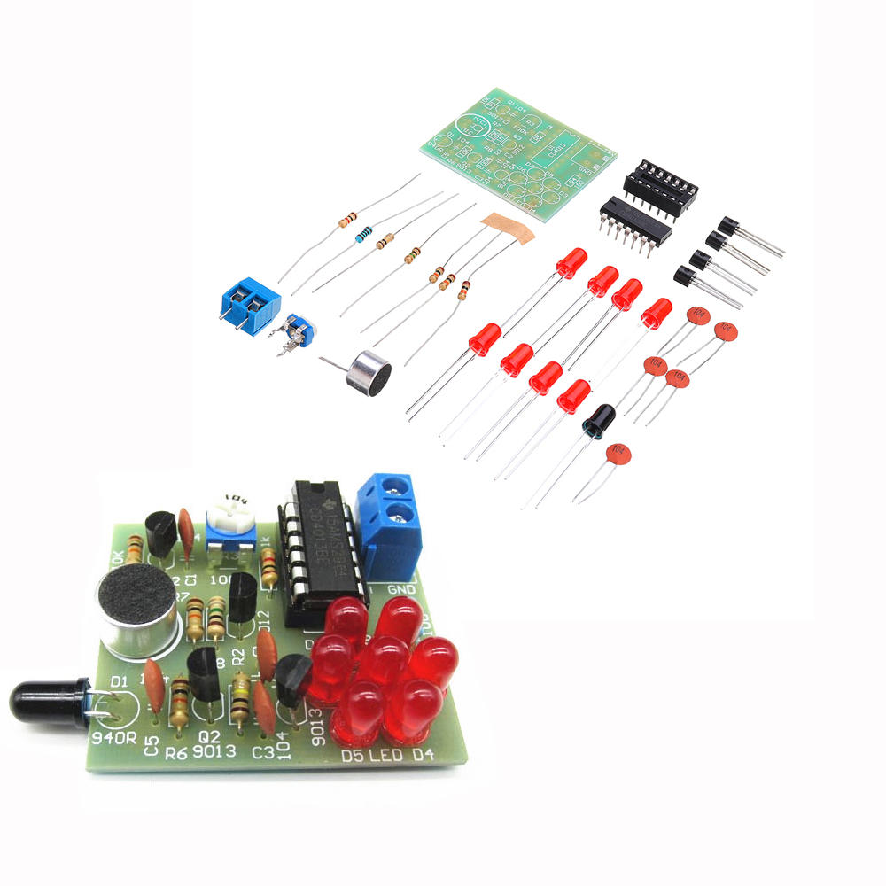
Compatibility
To confirm that this part fits your vehicle, please enter your vehicle's details below.
-
Year:
Select
-
Make:
Select
-
Model:
Select
-
Submodel:
Select
-
Trim:
Select
-
Engine:
Select
- Clear All
This part is compatible with 0 vehicle(s).
Show all compatible vehicles
Show all compatible vehicles
This part is compatible with 1 vehicle(s) matching
This part is not compatible with
Recent searches
- Year
- Make
- Model
- Submodel
- Trim
- Engine
Description:
CD4013 is a dual D flip-flop consisting of two identical and independent data flip-flops. When the rising edge of the clock is triggered, the logic level added to the D input terminal is sent to the Q output terminal. Setting and resetting are not related to the clock, but completed by the high level on the set or reset line, respectively. This circuit uses a D flip-flop in the double D flip-flop, which is connected to RS flip-flop. When the power supply is switched on, the differential circuit composed of C2 and R2 generates a high-level differential pulse to the IRD end of U 1, forcing the circuit to reset, and the low-level output of the first end is sent to the base of Q4 transistor, Q4 is cut off, and the light-emitting diode is not bright. When the lighter is close to 940 infrared receiving diode, the infrared diode is in reverse breakdown conduction, the resistance value suddenly decreases, the base of Q1 presents a low level state, the transistor Q1 is turned on, and the high level pulse generated by collector is sent to the ISD end of U1, so that the 1Q end is high anyway. It is sent to the base of Q4 through resistance R5, and Q4 is turned on. Light diodes shine. This process is equivalent to lighting a candle with a match. At this time, even if the lighter leaves the infrared receiver, the circuit state will not change, and the light-emitting diode will remain bright.
When the electret microphone MIC is blown by the mouth, the audio signal output by the microphone MIC is amplified from C5 to Q2. After amplification, the signal drives Q3 to turn on and output pulse signal to the IRD end of U1. The trigger is reset, 1Q becomes low level, Q4 is cut off, and LED is extinguished to realize the effect of blown candle extinguishing.
Input voltage: DC 4.5-5.5V
Circuit Board Size: 4.3CM x 3.8CM
PCB Material: Glass Fiber
Circuit board function: simulate candle ignition, blow out the candle, interesting, realize the function of electronic candle.
Circuit Board Size: 4.3CM x 3.8CM
PCB Material: Glass Fiber
Circuit board function: simulate candle ignition, blow out the candle, interesting, realize the function of electronic candle.
Package Included:
1 x DIY Analog Electronic Candle Production Kit


