Price:
US$23.52 ~ 26.52
Compatibility
To confirm that this part fits your vehicle, please enter your vehicle's details below.
-
Year:
Select
-
Make:
Select
-
Model:
Select
-
Submodel:
Select
-
Trim:
Select
-
Engine:
Select
- Clear All
Show all compatible vehicles
- Year
- Make
- Model
- Submodel
- Trim
- Engine
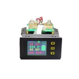
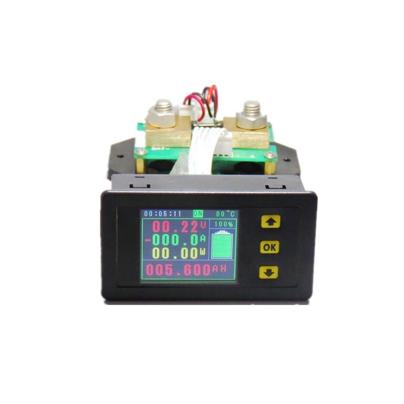
Specifications:


Note: If the voltage range of the tested battery (power supply) is between (6-75V) during the normal operation, it can use its own power supply wiring mode. First, adjust the jumper cap of the power supply selection interface to “2W”, and then connect it. The positive pole of the battery (power supply) is connected to the voltage measurement port “Bat+”, and the negative pole of the battery (power supply) is connected to the shunt “BAT-”. The positive and negative poles of the power supply should not be connected wrongly or reversed. Connect the positive pole of the battery (power supply) to the positive pole of the load, and connect the negative pole of the battery (power supply) to the negative pole of the load through the other end of the shunt; the positive pole of the charger is connected to the positive pole of the battery, and the negative pole of the charger passes through the shunt. One end is connected to the battery (power supply).
(2) External power supply wiring diagram

Note: If the voltage range of the tested battery (power supply) during normal operation is not between (6-75V), the external power supply connection mode can be used. The external power supply voltage range is (6-75)V. The power supply selection interface jumper cap is firstly used. Adjust to "3W", then connect the positive terminal of the battery (power supply) to the voltage measurement port "Bat+" at the time of connection, connect the negative pole of the battery (power supply) to the shunt "BAT-", and the positive and negative poles of the power supply should not be connected. Wrong or reversed. Connect the positive pole of the battery (power supply) to the positive pole of the load, and connect the negative pole of the battery (power supply) to the negative pole of the load through the other end of the shunt; the positive pole of the charger is connected to the positive pole of the battery, and the negative pole of the charger passes through the shunt. One end is connected to the negative pole of the battery (power supply) phase.
(3) Electrical relay wiring instructions

Note: The relay's working power is provided by an external power supply. If the relay is connected, an external power supply with the same working voltage as the relay must be provided, and the power supply status of the instrument is adjusted to the “3W” state. Connect the control port of the relay to the interface of the controller, and then connect the negative pole of the power supply to the “BAT-” position of the shunt through the normally open or normally closed port of the relay, and the wiring of other parts will not change.


