Price:
US$43.99
Free Shipping
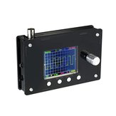
DSO328 Portable Digital Oscilloscope 2.4″TFT 1Msps 0-200KHz STM32 with Crocodile Clips Probe Case


Compatibility
To confirm that this part fits your vehicle, please enter your vehicle's details below.
-
Year:
Select
-
Make:
Select
-
Model:
Select
-
Submodel:
Select
-
Trim:
Select
-
Engine:
Select
- Clear All
This part is compatible with 0 vehicle(s).
Show all compatible vehicles
Show all compatible vehicles
This part is compatible with 1 vehicle(s) matching
This part is not compatible with
Recent searches
- Year
- Make
- Model
- Submodel
- Trim
- Engine
Description:
This mini oscilloscope is designed for electronic hobbyists to learn about electronics, soldering, programming and STM32. It contains main controller board, TFT LCD and other electronic components to DIY a functional mini digital oscilloscope.
Feature:
Use STM32 Chip. It runs faster than DSO138 and a good handle of data.
Pre-programmed. The controller board is programmed and tested before leaving factory. It is high quality and safe to use.
Full of Fun. It is a DIY kit and fun to make your own oscilloscope. Especially suitable for who are interested in soldering and STM32.
With Cool Black Case. Unlike DSO138, this DS0311 is with a cook black case, which makes it convenient to use in teaching and testing.
Notice: This oscilloscope requires DC 9V 200mA power supply (no more than 10V, or it may be burned)
Specification:
Input impedance: 1MΩ
Analog Bandwidth: 0 – 200 KHz
Maximum input voltage: 50Vpp (1: 1 probe), 400Vpp (10: 1 probe)
Maximum real-time sampling rate: 1Msps
Comes 1Hz /3.3V square wave test signal source
Accuracy: 12Bit
Sampling buffer depth: 1024 bytes
Vertical Sensitivity: 5mV/Div – 20V/Div
Adjustable vertical displacement, and with instructions
Coupling modes: DC / AC / GND
The horizontal time base range: 10μs / Div – 50s / Div (1-2-5 progressive manner)
With automatic, regular and one-shot mode, easy to capture the moment waveform
Available rising or falling edge trigger
Adjustable trigger level position, and with instructions
Observable previous trigger waveform (negative delay)
It can freeze at any time waveform display (HOLD function)
Connection:
Power Supply: DC 8V-10V, recommend DC 9V, no more than 10V
Probe: connect the probe to BNC
Button Function:
[V/DIV]: Selection for Sensitivity and Vertical position
[SEC/DIV]: Selection for time base and horizontal position,
[TRIGGER]: Selection for Trigger mode, Trigger Level or Trigger Edge
[OK]: Press once to entert HOLD function, second press to exit HOLD function
[ADJ]: Arrow key, turn left and right to select parameters Selected parameter will be highlighted
[COUPLING SWITHC]: Coupling can be switched to DC, AC or GND. When it is switched to GND, the oscilloscope’s input is disconnected from external input and is connected to the ground, aka input is 0 V
Probe-compensated adjustment:
Adjust trimmer capacitor C3 and C5:
a)Connect the probe’s RED clip to signal output terminal, black clip not connected
b)Power on the oscilloscope to start, press [ADJ] knob for 3 seconds. Tthe bottom of the screen shows the output of the test signal amplitude, and then press [ADJ] to adjust amplitude to 0.1V.
c)Set sensitivity to 50mV, adjust trigger level to make the waveform stable.
d)Adjust C3 to make the waveform right-angled. C3 adjustment is finished.
e)Press [ADJ] to adjust amplitude to 3.3V, and set sensitivity to 1V, adjust C5 to make the waveform right-angled.
Package Includes:
1 x DSO328 LCD oscilloscope
1 x Test Probe
Details Pictures: