Price:
US$8.99
Free Shipping
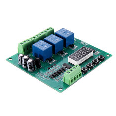
YYS-4 3 Channel Programmable Relay Control Module Trigger Delay/Timer/Self-latching/Interlock Switch Relay Board


Compatibility
To confirm that this part fits your vehicle, please enter your vehicle's details below.
-
Year:
Select
-
Make:
Select
-
Model:
Select
-
Submodel:
Select
-
Trim:
Select
-
Engine:
Select
- Clear All
This part is compatible with 0 vehicle(s).
Show all compatible vehicles
Show all compatible vehicles
This part is compatible with 1 vehicle(s) matching
This part is not compatible with
Recent searches
- Year
- Make
- Model
- Submodel
- Trim
- Engine
Features:
– This programmable control board is designed with 3-channel relays.
– It supports time delay/interlock/self-latching/sequential starting.
– The module is powerful and convenient to operate.
– There are six kinds of commonly used functions to meet the demand of more applications.
– It can be used to control solenoid valves, pumps, motors, light belt, etc.
Specification:
Model: YYS-4
Input voltage: DC/AC 7V~30V
Output power: Can control DC or AC loads within 5A
Time range: Adjustable from 0.1 seconds to 999 minutes
Wiring:
1. AC/DC: Input power supply DC/AC 7V~30V
2. IN1: Signal input 1 (negative trigger)
3. IN2: Signal input 2 (negative trigger)
4. IN3: Signal input 3 (negative trigger)
5. NO: relay normally open interface, relay are disconnected before energized, and connected to COM after energized.
6. COM: relay COM interface
7. NC: relay normally closed interface, connected to COM before relay is energized, and disconnected after relay is energized.
Functions:
Function can be set freely by user;Set parameters can be saved after power failure.
P–1: send signal 1, relay 1 is energized till A time automatically stop;
send signal 2, relay 2 is energized till B time automatically stop;
send signal 3, relay 3 is energized till C time automatically stop;
There is only one relay at work at the same time.
P–2: send signal 1, relay 1 is energized till A time automatic stop, then relay 2 is energized till B time stop, then relay 3 is energized till C time stop;Send signal 1 again, repeat the former action.
Send signal 2, relay 1 is energized till A time automatic stop, then relay 2 is energized till B time stop, then relay 3 is energized till C time stop;then relay 1 is energized till A time stop…an infinite cycle.
Send signal 3, relay 1 is energized for 100ms then stop, wait A time; relay 2 is energized for 100ms then stop, wait B time; relay 3 is energized for 100ms then stop, wait C time; relay 3 is energized for 100ms then stop, wait A time; relay 1 is energized for 100ms then stop… an infinite cycle.
P–3: After powered on, relay 1 is energized for A time then stop, wait C time;relay 2 is energized for B time then stop, wait C time;Relay 1 and relay 2 work in turn;During the period of relay 1 and relay 2 are energized, relay 3 stops;During the period of relay 1 and relay 2 are de-energized,relay 3 is energized;
P–4: send signal 1, relay 1 will be energized after a delay of A time, then relay 2 will be energized after a delay of B time, and then relay 3 will be energized after a delay of C time;
send signal 2, relay 1 will be de-energized after a delay of A time, then relay 2 will be de-energized after a delay of B time, and then relay 3 will be de-energized after a delay of C time;
send signal 3, emergency reset signal;
P–5: send signal 1, relay 1 would work;send signal 1 again, relay stops; sending signal 2, 3 is respectively corresponding to each relay action; 3 channels are independent from each other.
P–6: send a signal 1, relay would work, while other relays stop;send signal 1 again, relay stops;sending signal 2, 3 is respectively corresponding to each relay action;There is only one relay at work at the same time.
Button setting instructions:
After powered on, it shows "—-" to enter standby state;
press K1,
screen display: P–1: K2 and K3 adjust mode
Press K1 again, screen display: A001: K2 and K3 adjust the first time A, K4 adjust decimal point (time units)
Press K1 for the third time, screen display:B001: K2 and K3 adjust the second time B, K4 adjust decimal point (time units)
Press K1 for the forth time, screen display:C001: K2 and K3 adjust the third time C, K4 adjust decimal point (time units)
Press K1 for the fifth time, it shows "—-" to enter standby state;
Decimal point and unit of time:
XX.X: The decimal point in the "tens" position, timing range: 0.1 seconds ~ 99.9 seconds.
XXX: No decimal point, timing range: 1 second~9999 seconds.
XXX.: The decimal point in the units position, timing range:1 minute ~ 999 minutes.
Package Included:
1 x YYS-4 3 Channel Programmable Relay Control Module